 1. We‘ll start our front suspension rebuild process with the removal of the brake components. What you have left is all suspension from the spindle back to the frame.
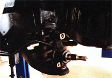
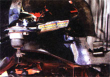
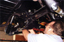
 2. After removing the shock absorber, sway bar link, and cotter pin from the ball joint nut, loosen it to about halfway off the threaded area. You can then use the spring‘s tension to you advantage to break the spindle apart from the ball joint with a pickle fork and hammer.
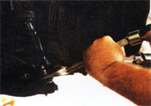
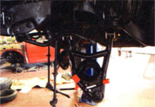
 3. The spindle is now completely removed. Care must be taken as the lower A-arm is lowered farther to allow removal of the coil spring, as there is still some tension in the spring.
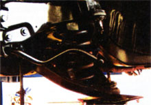
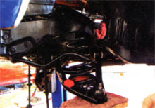
 4. With the spring removed, the upper and lower A-arms swing freely. Remove the lower A-arm bolts at the frame and the A-arm will swing out of its mounts. The upper A-arm can be removed by loosening the two adjusting bolts through the cross-shaft.
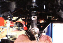
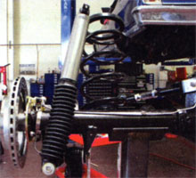
 5. John begins the front suspension assembly process with the installation of the Global West tubular upper A-arm. The frame mounting location is a direct fit into the billet cross-shafts. John leaves about half of the alignment shims between the cross shaft and frame mount until the car goes up on the alignment rack.
 6. Install the lower tubular A-arm by sliding the Del-a-lum bushings into the stock frame mounts and securing with the new bolts and locking nuts provided with the A-arms.
 7. Slide the front spring into the frame and make sure it properly seats in the frame pocket. Bring the lower A-arm to the spring and begin to apply tension with a jack.
 8. With the spindle attached to the lower A-arm, continue to raise the assembly to the upper A-arm ball joint until the threads are through the spindle. Tighten the ball joint nuts and torque to 60 lb-ft.
 9. The Edelbrock IAS shock absorbers can now be prepped and installed. Before sliding them into position through the opening in the lower A-arm, the dust covers are secured to protect the shock shafts from road grime.
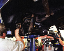 10. To make the project easier, we completely removed the entire third member from under the car. This allows better access for the installation of the new suspension and brake components. Removing the driveshaft, shocks, and the four control-arm-to-frame mounting bolts allowed the entire assembly to be lowered slowly and out from under the car. Where possible, two sets of hands will greatly improve the process and your attitude.
 11. The Global West tubular front A-arms are in place and ready to begin the brake installation. The anticipated performance enhancements are almost visible when compared to the stock system.

 12. The complete front suspension combines Global West tubular A-arms and spring with Baer Brakes‘ Serious Street Disc conversion. For comparison, check out our “Before” and then “After”. Any questions? We didn‘t think so.
 13. Here is the complete rearend assembly removed from the car. Once again we found parts we forgot to get, and a quick trip to Original Parts Group (OPG) scored us new upper control-arm polyurethane bushings and coil-spring insulation pads. You can see the originals are shot.
 14. With all our measurements completed the rearend was stripped down for detailing.
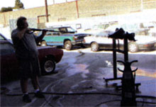
 15. After drying from the power wash, the complete rearend housing was treated to a fresh coat of gloss-black paint. The added effort sure improves the overall look prior to the start of reassembly.
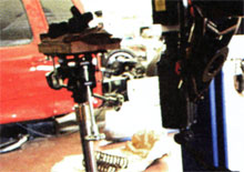
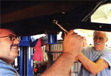
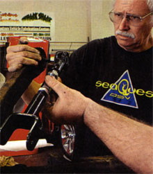 16. Prior to installation, Paul and John match the adjustable Global West upper control arm to stock unit for length. This is used for a starting point, and during later track events we can adjust it slightly to dial-in for absolute effectiveness.
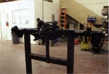
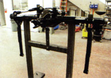 17. With the third member secured in a holder, both the upper and lower Global West control arms are installed. The spherical bearing ends on both sets of control arms can be seen prior to installation into the frame.
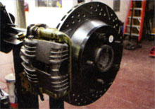 18. The Baer Brake Rod & Drag read-disc-brake conversion is installed along with hydraulic lines from OPG.
 19. Edelbrock IAS shock absorbers along with Global West ?-inch-drop rear springs are the final parts to bolt on the third member before it is reunited with the car. New insulation pads from OPG are added to the top of the springs, and the complete unit is now maneuvered under the car.
 20. The upper and rear controls are guided into place on the frame. The rear control-arm mounting braces are positioned, and the entire assembly is secured with the longer bolts and self-locking nuts that were provided. Bolt torque is to 70 lb-ft.
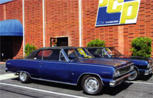 21. Leave it to John and the guys to provide a real comparison. They supplied a customer‘s bone-stock Chevelle to compare ride height and stance to ours. Even with a 2-inch larger overall wheel and tire package, it sits slightly lower than the stocker, and we know it handles better.
 22. With the spring indexed into the frame pockets, the entire rearend is jacked up into position while guiding all four control arms into place. Again, it is better to have at least two people for this portion of the job to make sure everything lines up on the first try. Slide the control-arm bolts in place and mount the shocks to frame to support the entire assembly.
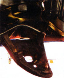
 23. This is a close-up view of the frame connectors in place. They provide a superior means of tying the entire assembly together as one unit.