 1. We started the conversion process with the front brakes.Many of you will recognize this as the antiquated system that will be replaced. After securing your car on a hoist or jackstands, start by pulling the drum off the hub and then removing that hub by pulling the dust cap, cotter pin, and spindle nut.
 2. With the drum and hub removed, the brake shoes and springs are exposed. Prior to their removal, detach the wheel cylinder from the line.
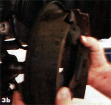
 3. The two backing-plate bolts and brake-spring anchor pin, which is also an attaching point, are now exposed. Remove the springs from the anchor pin and loosen it along with the backing-plate bolts. The backing plate with the springs and shoes can now be removed from the spindle.
 4. The Baer Serious Street system is mounted with 1/2-inch bolts. Some older cars used 7/16-inch bolts, and if that‘s that case with your car, the holes need to be enlarged using with a 1/2-inch drill bit, or Baer has a 1/2-inch reamer available. The spindle should also be thoroughly cleaned prior to reassembly.
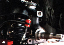
 5. The caliper bracket is positioned so that the caliper will mount to the rear of the vehicle. Bolts of different length are used to mount the bracket, and since the Chevelle is a front steer car, the longer bolt goes to the front. Secure and torque to 95 ft-lb.
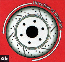
 6. Direction of rotation is vital to the proper operation of the Baer Serious Street brake system. Since the rotors are directionally ventilated, they must rotate in the correct direction to obtain necessary airflow for cooling.
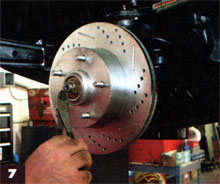 7. With the proper rotation noted, the hubs are installed onto the spindle with the keyed washer and castle nut. The hubs come preassembled from Baer with Timken bearings, races and National seals packed in Redline synthetic grease. Baer stresses to only tighten just past finger-tight while rotating the rotor to allow for thermal expansion.
 8. Calipers are also marked for left and right to simplify installation. Each caliper comes loaded with high-metallic pads (same as the original equipment on ZR-1 corvettes) and slide right in place. Secure with the supplied 9/16-inch bolts and torque to 105 ft-lb. Install the supplied braided hose and banjo-style fittings, and the front is ready for the proper bleeding procedure when the balance of the has been completed. Readers will also note new Global West Suspension tubular control arms installed at this point.
 9. The old master-cylinder pushrod has to be disconnected from the brake pedal inside the car by pulling the keeper off the clevis pin. With that loose, we removed the one fluid line and that two attaching bolts. The result was an open hole through the firewall and four mounting holes to which we will add new studs.
 10. The new power brake booster that Baer supplied matched up perfectly to the four mounting studs. After feeding the pushrod through the firewall, the power booster is positioned over the mounting studs and secured.
 11. The new dual-reservoir master cylinder is mounted to the power booster and secured with the provided washers and nuts. A 10-inch brake line was made to go from the front (smaller) reservoir to the Baer adjustable proportioning valve, and then to the new P{E front-to-rear brake line, which supplies fluid to the rear system. The rear (larger) reservoir on the master was plumbed to the factory T-fitting that supplies both front calipers.
 12. This is the stock rear brake prior to the start of our conversion to the Rod & Drag disc system. Remove the drum to allow access to the axle and backing plate.
 13. To remove the axles on most GM rearends of this era, you need to access the C clips found in the center section. After removing the cover and draining the fluid, carefully remove the bolt that retains the cross-shaft and slide one axle at a time in toward the center. The C clip can easily be pulled out by hand or with needle-nose pliers. The photo shows one C clip in and one out (arrow).
 14. With the C clip removed the axles can be pulled out from each side. To remove the brake backing plate, you will need to first disconnect the brake line from the wheel cylinder, the emergency brake cable from the frame, and the four bolts as shown.
 15. With the brake backing-plate bolts removed from the axle housing, the entire backing plate with shoes and springs will slide off the axle.
 16. After cleaning the axle housing surface and inspecting the axle bearings and seals for wear, begin the conversion assembly process by mounting one of the Baer-provided intermediate Brackets to the housing. Care must be taken as to the final positioning of the caliper in this step, as brackets are drilled for two sets of mounting options. The Chevelle has calipers mounted at the 4 o‘clock position on the driver side and 8 o‘clock position on the passenger side. Torque bolts to 35 ft-lbs.
 17. A very important step in the conversion is to measure the axle flange outer diameter. It must be 5.9 inches or less to properly allow the rotor to mount to the axle. If it is larger, you must have a machine shop cut down the axle as shown.
 18. Install the axle back into the housing and attach the C clip in the reverse manner. Be careful to keep gears and spacers in line as the cross-shaft slides back in place.
 19. Rotors are clearly marked for left- and right-side installation. Slide the rotor on the axle and hold it in place with two lug nuts tightened to finger-tight only. Check the length of the studs because you may need (as we did) to install slightly longer studs to accommodate the rotors and for custom wheel installation later.
 20. The caliper is now installed on the intermediate bracket. Secure with the provided bolts and take measurements on both sides of the caliper to the rotor. There must be a minimum of 0.030 inch on each of the four sides. With proper spacing, torque caliper bolts to 85 ft-lbs.
 21. Brake lines are of the factory style adapted to the Baer brake caliper and lines. The OPG factory-style line has been installed on the rearend housing, and a 90-degree curve to the front of the car bent to connect to the Baer-provided line connection and stainless steel braided hose.
 22. Because our Chevelle was also receiving a bolt-in suspension upgrade from Global West Suspension, we did have the rearend out from under the vehicle. The rear brake conversion is now finished and ready for a complete and thorough bleeding.
 23. Back under the car, all lines and cables are installed. The final check is to review clearance of moving suspension parts, which in our case had space to spare. Bleed the brakes following Baer‘s instructions and get ready for miles of safe and serious stopping abilities.